I wish we lived closer, I'd come over and poke at it with you. Actually, I used to live a lot closer to you, but that doesn't help us much now!
I have a nifty recording digital 'scopemeter' that is very useful for times like this. It has two channels, so one can record the volts and the other can be used with an AC/DC current probe that clamps onto the lead (no cutting and splicing required). It would show us both readings while powering the plugs, running the starter, and after the machine was running. Handy.
I'd like to see the wiring diagram because I wonder if there is supposed to be some sort of ballast resistor in series with the plug feed that is now missing.
I know that the F350 glow plug control unit has such a resistor incorporated that looks like a piece of ribbon candy made from copper. It's meant to limit the current to the plugs. Those plugs drop resistance as they heat up so without a limiter in series, they'd run away and burn themselves out quickly.
I don't know if the 1010 plugs have the same characteristic or not. But, if they do, they would need such a limiting resistor or they'd burn out in a hurry.
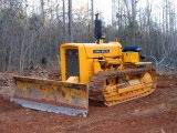
I'm sitting here thinking about that and wondering if there once was such a resistor on the 1010 that is now missing due to some wiring 'repairs' in the past. Perhaps the single battery cable was acting as a ballast resistor in place of a specific one, and now it's effectively gone since there's a second battery and cable in place.
I know. This gets us to the same thought as before, but with a possible explanation as to *why* you'd trip across the problem by simply adding a second battery in parallel with the first one. It's somewhat of a stretch since I'm basing the thought on some other design I've seen. But since it did come to mind, I thought I'd pass it along in case I might be onto something here....
Later!
Stan


