1010 reverser rebuilt still not moving.
-
pwright0001
- 40C crawler

- Posts: 18
- Joined: Fri Apr 13, 2012 1:03 pm
- Location: East Tn
1010 reverser rebuilt still not moving.
i have a 1010 crawler loader, that i have replaced all cluthches and plates in reverser. put all back together machine will still not move. I am wondering if the releif valve housing may be the problem. when you put the 90 psi and the 20psi releif valves along with their springs and shims in the valve body, there is no pressure on them. could thes valves or the housing be worn out ? when you install the center or the 100 psi releif valve with springs and shims it goes to the end of a round bore spot and stops therefore creating spring pressure. the 20 and 90psi valves go past the end of the round bore into an opening that leads to the cooling ines. With all valves and springs installed I can turn the valve body over backwards and using a small screwdriver slide the 20 and 90 valves atleast 1/2inch or more with no tension at all. I have also found another issue that may be causing the problem, I found this by looking at another post on this message board.post is Called 350 reverser rebuild . My clutch valve lever has about the same amount of wear as the pic that user,posted. I hope that someone may have any information for me, and thanks in advance. Could some one please let me know how to post some pics to this post? [/img]
-
Paul Buhler

- 350 crawler

- Posts: 994
- Joined: Wed May 21, 2008 6:25 pm
- Location: Killington, VT
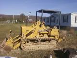
Hi: To post picture, I use Photobucket. I joined the site and then uploaded the picture(s) that I wanted to use. I log in and use the "IMG Code" to copy and paste a link here. I pasted a picture of my dozer and the  codes came with the paste.Good luck. Paul

Paul Buhler
Killington, VT
420c 5 roll with 62 blade, FOPS, and Gearmatic 8a winch
Killington, VT
420c 5 roll with 62 blade, FOPS, and Gearmatic 8a winch
Here is a step by step tutorial to post from photobucket if you need it:
http://www.jdcrawlers.com/messageboard/ ... php?t=3690
http://www.jdcrawlers.com/messageboard/ ... php?t=3690
(1) JD Straight 450 crawler dozer with manual outside blade; (2) JD 2010 diesel crawler loaders; (1) JD 2010 diesel dozer with hydraulic 6-way blade; (2) Model 50 backhoe attachments, misc. other construction equipment
-
pwright0001
- 40C crawler
- Posts: 18
- Joined: Fri Apr 13, 2012 1:03 pm
- Location: East Tn
-
pwright0001
- 40C crawler
- Posts: 18
- Joined: Fri Apr 13, 2012 1:03 pm
- Location: East Tn
1010 reverser valve body
does anybody out there have a reverser valve body from a 1010 crawler, that is removed from the housing? I need to know something about the view of 20 & 90 psi releif valves from the rear side.
Its not a sin to be poor, Just inconvenient !
-
jdemaris
Re: 1010 reverser valve body
These is one for sale on Ebay right now. Maybe you can get the owner to take a close look for you (but I doubt it). With those three valves, there isn't much to see. All three go in from the bottom with the little stubs facing down. Then the springs, shims, and caps. Same of the 20, 90, and 100 PSI valve.pwright0001 wrote:does anybody out there have a reverser valve body from a 1010 crawler, that is removed from the housing? I need to know something about the view of 20 & 90 psi releif valves from the rear side.
What is the history with your machine? Have you ever had it running or did you buy as a basket case? I ask because I've never seen those regulating valves cause any problems. All there is are three springs, three valve spools, and a few shims (or pennies stuck in). Main wear item inside that assembly is the clutch valve shift fork that gets badly worn.
When you put the reverser back together - but before you put the control assembly on - did you air-test the forward-reverse-return clutch packs via those two little tubes? Have you taken a pressure test in the clutch and lube ports? One big mistake I've seen made is to remove the lube-orifice from the input shaft and forget to put it back in. Another is to tighten/close the rate-of-shift screw. It turned in, the machine will not move.
-
pwright0001
- 40C crawler
- Posts: 18
- Joined: Fri Apr 13, 2012 1:03 pm
- Location: East Tn
1010 reverser valve body
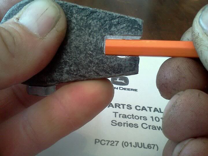
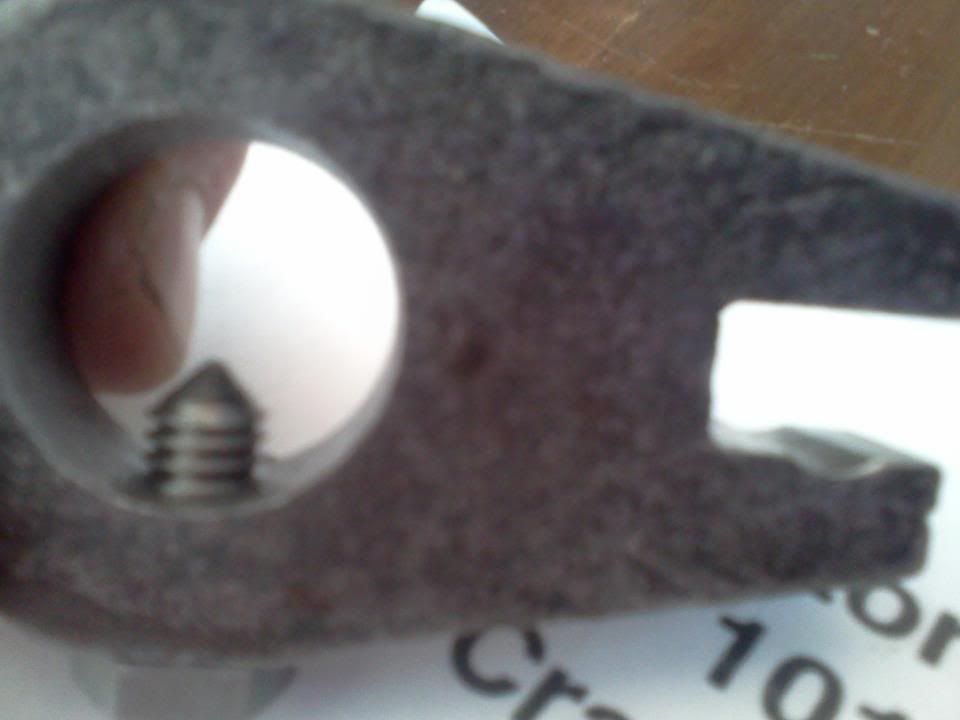
I have contacted the guy that has the one on ebay, guy isnt willing to flip it over and take a look. I need to know if when valves springs and shims are installed , if you can slide the 20 & 90 psi valves forward beyond the round bore area into the square ports where the cooler lines go. This was a very strong running and pushing machine, I have found a moon shaped wearspot on my clutch control lever, very similar to one i found on a 350c reverser rebuild post. here is the pic i found on here . 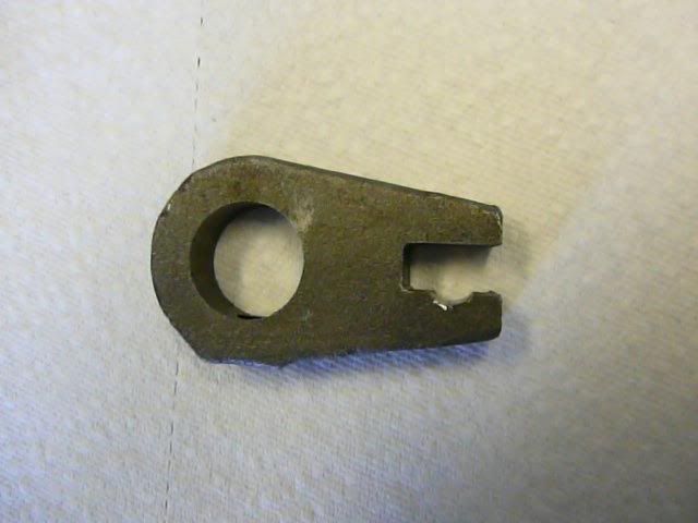
Its not a sin to be poor, Just inconvenient !
-
jdemaris
Re: 1010 reverser valve body
Yes, that is the clutch-control fork I mentioned in my post. It's the one part that tends to get a lot of wear inside that valve. I've welded up (or replaced) many.pwright0001 wrote: I have found a moon shaped wearspot on my clutch control lever, very similar to one i found on a 350c reverser rebuild post.
From what you describe, I don't believe there is anything wrong with your spool valves.
You didn't answer my previous questions. Did you check your clutch packs with air before you installed the control-valve-assembly? After assembly, did you do a clutch and lube pressure check? Also, did you have the lube-orifice out of the input shaft when the reverser was apart?
-
pwright0001
- 40C crawler
- Posts: 18
- Joined: Fri Apr 13, 2012 1:03 pm
- Location: East Tn
not sure how to air test . when you say lube orfice , do you mean the regulating plug ? the only thing i could do to test pressure was to pull the electric sending unit out with engine running, and there was no fluid there. also took cooling lines loose with engine running , also no fluid there either. will the air test reveal the condition of the rings on the pistons that engage clutch packs?
Its not a sin to be poor, Just inconvenient !
-
jdemaris
When the control-valve assembly is off the reverser - there are two steel tubes sticking out the side with a dowel/port inbetween them. So, three holes. If you blow air into one tube the forward clutch pack engages. Blow air into the other tube and the reverse clutch pack engages. If you blow air into the center port - it releases the clutches. The two tubes have two o-rings one them - one on each end and I assume you replaced them. If you forget the o-rings, you'd have no clutch pressure. They connect the reverser control valve to the clutch manifold inside the reverser. The center-dowel lube-release port also has an o-ring.pwright0001 wrote:not sure how to air test . when you say lube orfice , do you mean the regulating plug ? the only thing i could do to test pressure was to pull the electric sending unit out with engine running, and there was no fluid there. also took cooling lines loose with engine running , also no fluid there either. will the air test reveal the condition of the rings on the pistons that engage clutch packs?
The "lube-orifice" is a steel pipe-plug with small hole in the middle of it. It screws into the end of the reverser input shaft. New input shafts don't come with it and if someone forgets to install it - you get no clutch pressure.
That sending unit is for lube-pressure which only runs around 20-30 PSI as I recall. There is pipe-plug you remove to check clutch pressure. Takes 1/8" piipe thread. A grease-gun hose hooked to a 150 -200 PSI gauge works fine.
-
pwright0001
- 40C crawler
- Posts: 18
- Joined: Fri Apr 13, 2012 1:03 pm
- Location: East Tn
so when you put airpressure on these tubes, one at a time, should it hold air pressure ? or will the the air be able to escape ? What im asking is , if you would have to keep constant air flow to keep the clutches engaged or could you fill the pistons with air and that keep them engaged ?When the control-valve assembly is off the reverser - there are two steel tubes sticking out the side with a dowel/port inbetween them. So, three holes. If you blow air into one tube the forward clutch pack engages. Blow air into the other tube and the reverse clutch pack engages. If you blow air into the center port - it releases the clutches. The two tubes have two o-rings one them - one on each end and I assume you replaced them. If you forget the o-rings, you'd have no clutch pressure. They connect the reverser control valve to the clutch manifold inside the reverser. The center-dowel lube-release port also has an o-ring.
Its not a sin to be poor, Just inconvenient !
-
pwright0001
- 40C crawler
- Posts: 18
- Joined: Fri Apr 13, 2012 1:03 pm
- Location: East Tn
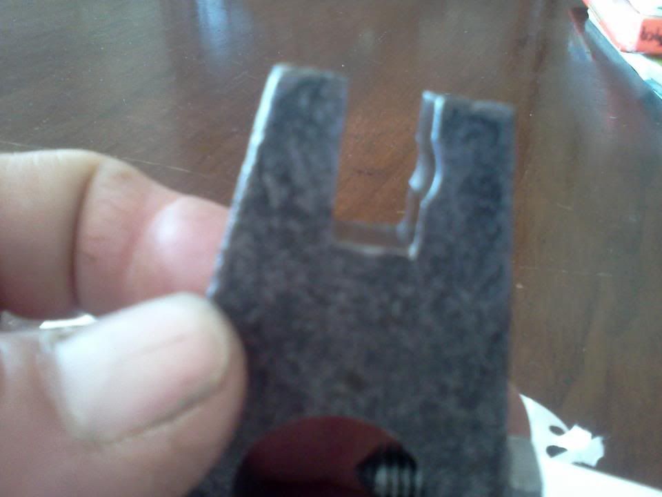
pics of my clutch control lever
could this be enough wear to stop the fluid from flowing ? 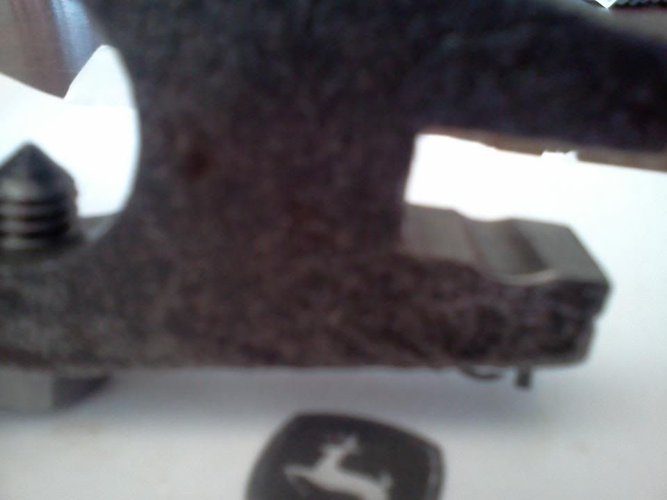
Its not a sin to be poor, Just inconvenient !
-
jdemaris
Re: pics of my clutch control lever
No, it's worn but not that worn.pwright0001 wrote:could this be enough wear to stop the fluid from flowing ?
When you put air to one of those tubes - there will be slight leakage inside the reverser- but not much. The oil-manifold has steel rings that are meant to seal oil - not dry air - so they will leak a little. If you put air to the tube and the clutch engages with no loud hissing inside the reverser - it's working.
-
pwright0001
- 40C crawler
- Posts: 18
- Joined: Fri Apr 13, 2012 1:03 pm
- Location: East Tn
-
pwright0001
- 40C crawler
- Posts: 18
- Joined: Fri Apr 13, 2012 1:03 pm
- Location: East Tn
Back with results from the air test
Ok so i went outside and put air pressure to the tubes, the uppper tube when pressurized will hold air and engage clutches to release them i put air to the center tube.. ok now reverser is disengaged. when lower tube is pressurized i hearair inside and front shaft doesnt feel like it is engaged. But would this explain no fluid to cooling lines and no oil to sending unit ?
Its not a sin to be poor, Just inconvenient !
Who is online
Users browsing this forum: No registered users and 87 guests