General help and support for your Lindeman through 2010 John Deere crawler
-
Gil
- 1010 crawler

- Posts: 362
- Joined: Fri Dec 14, 2007 3:19 pm
- Location: Pennsylvania
Post
by Gil » Mon Jul 14, 2008 8:20 pm
I have the tracks off of my JD440ICD and I wanted to touch up the front rails so that the idler wheels would run true. I started building up a weld on the rail edges but I don't know what clearance is specified between the rail and the idler bracket guide.
Also since there is wear on the guide, I am not sure how much of the wear has come from the rails and how much from the wearing of the guide. Does anyone know the dimensions between the set of rail edges? Is there a dimensional drawing anywhere? Thanks.
This is a picture of the current project. Since I had it all torn down I thought a little paint would be appropriate.
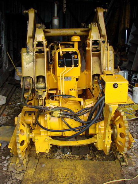
JD440-ICD loader; JD440-IC bulldozer; JD440-ICD backhoe; JD440-I backhoe; JD440-I tractor; + five recumbent JD440-ICs
-
lizrad999
- 430 crawler

- Posts: 59
- Joined: Fri Dec 28, 2007 4:36 pm
- Location: Memphis
-
Contact:
Post
by lizrad999 » Mon Jul 21, 2008 7:23 am
Gil, My rails and front brackets were worn causing quit a bit of slop in the front. I found that using a straight edge on the rails (over the worn area) will give a pretty good idea of the amount of metal missing. I ended up cutting a piece of "stretched cresent shaped" steel and welding it in place. You kind of have to feather the edges and fill with weld, but you can always dress it with the grinder to make it flush and smooth.
As for the brackets, I was a little reluctant to try welding on them (they seemed to be cast) with my MIG. So, I lightly ground off any shape edges and that was all I could do with them.
In thinking about it now, a fellow could make a little plate that fit over the worn area but had ears to bolt on with the mounting bolts, OR it could be tapped and screwed on from underneath. Make a little wear plate that could be changed whenever..
Just a thought.
-
Gil
- 1010 crawler
- Posts: 362
- Joined: Fri Dec 14, 2007 3:19 pm
- Location: Pennsylvania
Post
by Gil » Mon Jul 21, 2008 7:58 am
You mentioned using a straight edge on the good part of the rails. It appears to me that the original rails step in at each side in the area where the front idler runs. My best guess is that they were originally 10 1/4" between outside edges. Of course with wear on the original idler brackets things may fit just as well without the indent.
I just resurfaced my rails and left about 1/4" clearance between the idler bracket and the rails. I have no idea if this is close to spec.
Replaceable rail tips would be a great idea. Maybe Lavoy would want to design and make a bunch up and sell them to us more metal working challenged folk.
JD440-ICD loader; JD440-IC bulldozer; JD440-ICD backhoe; JD440-I backhoe; JD440-I tractor; + five recumbent JD440-ICs
-
lizrad999
- 430 crawler
- Posts: 59
- Joined: Fri Dec 28, 2007 4:36 pm
- Location: Memphis
-
Contact:
Post
by lizrad999 » Mon Jul 21, 2008 11:57 am
Let's assume the rails are sitting as they would on the machine.
If you hold the straight edge along the side of the rail, yes there is a "step in" of just under 1/4" before you get to the end. Now, if you roll the straight edge up under that lip (keeping it horizontal), that is where I measured to get a ballpark idea of what was missing. The piece I added was 1/8" and it was plenty.
My thoughs are that there is (at times) quite a bit of weight on the front wheel which is being transfered to that worn area. Building it up would be about the only option. To fabricate a universal fix that could support the weight would be daunting.
When it comes to the specs, I think "close" is close enough.
Who is online
Users browsing this forum: No registered users and 147 guests